Logitech’s bluetooth audio receiver is a great device. It has good range, sound, and build quality. The original plan was to put it into my car to add bluetooth reception, but that plan disappeared when it turned into a install-a-new-stereo project. So I had a nice piece of equipment that didn’t have a home until my roommate’s older stereo in the living room popped into mind. One minute later and this old stereo gained a new feature. The only problem with this setup is ability to turn on or off a the stereo automatically.
I’ll just assume you’re as impatient as me, so here’s a video of the end result!
When I approached my roommate about taking apart his stereo and drilling holes into it, he understandably said “no.” If I couldn’t hook into the power switch directly, then what was I to do?
Infrared, that’s what. Even twenty year old stereos have infrared control and his stereo was no exception. I could sniff his IR remote’s commands and replicate them in software with an AVR. The bad news was the remote had been lost and replacements were expensive enough to squash the project.
I was lost without a known-good source of infrared commands. I needed to find a Panasonic N2QAGB000002 remote for the Panasonic SA-AK33 stereo or find someone who already described the remote’s protocol. Unfortunately used remotes were too expensive and web searches didn’t find anything describing the remote in detail. Generic IR protocol descriptions suggested the Japanese preferred 38khz as the carrier frequency. There are a few different Japanese IR protocols and many timing derivatives, so nothing more could be gleaned without hardware.
I found gold after some extended searching; someone had captured the N2QAGB000002 and submitted timing information to LIRC. This capture provided me with enough info to control the stereo.
I first found the capture with a comment describing the protocol as REC 80 encoded. This is incorrect. The protocol is more similar to NEC:
The N2QAGB000002’s format differs from pure NEC in a few ways:
Like NEC, logical one is one BW mark followed by a three BW space; logical zero is one BW mark and one BW space.
The address (first three bytes) is 0x400405. The command follows immediately after. Complete details, including command codes, can be found in LIRC’s N2QAGB000002 config file.
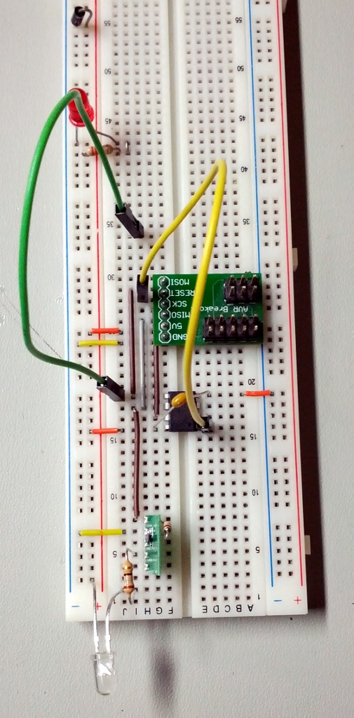
With the infrared research complete and verified with an Arduino, it was time to breadboard a device that would fit into the Logitech bluetooth receiver. Size was the biggest factor and I had some ATtiny25s devices in my parts bin. It’s a bit overkill (the binary clocks in at 514 bytes) but the extra features and breathing room was certainly welcome. I threw it on a breadboard along with a N-FET (FDN337N) low-side switching an IR LED (TSHA5502). Any generic transistor and IR LED will work, but these were what I had sitting on my bench. The gate (base if you’re using a BJT) of the N-FET is attached to the AVR’s PB1/OC0B pin and modulated with hardware PWM at 38khz for the IR carrier frequency. The firmware turns PWM on and off to send mark and space bits.
It was time to get some input with the output done. The Logitech receiver has two LEDs on the board; one red LED and one green LED. The red LED is lit when the device is idle. The green LED quickly blinks when a new device is being configured (the connect button was pressed) and is solid when a device is connected to it. The idea is to attach to the green LED output and detect for solid green.
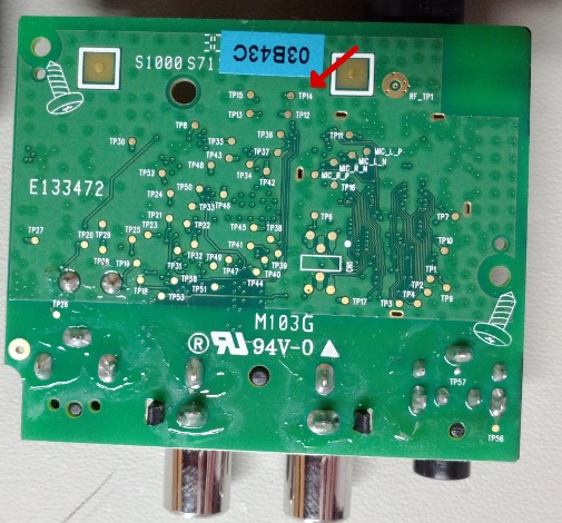
Probing around the receiver produced Test Point #14. TP14 floated when the green LED was not being driven and was pulled down to 0.5 volts when it was. Success: we can use the internal pullup on the AVR and get a digital input of the green LED state. Any simple low-pass filter will take out the blinking-LED state (I used a dumb 500ms polling debounce). My firmware uses the AVR’s PB0 as the LED sense.
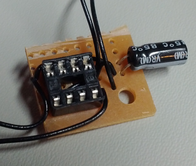
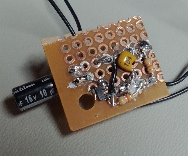
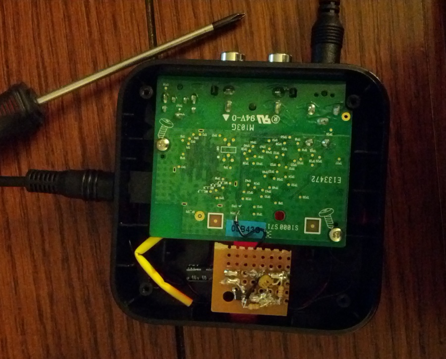
I was a bit impatient at this point, so I sawed off a bit of protoboard and started throwing components on it. This turned out fairly well. I even managed to solder down the SuperSOT FET right onto 0.1" pads. I ran out of my preferred alcohol bath, there’s some residue left over from the only alcohol I had left. Believe it or not, this ugly board works!
I drilled a hole in the side of ABS case and popped in a 3.5mm TRS jack for the IR LED output. Then a current limiting resistor was added in-line to save space.
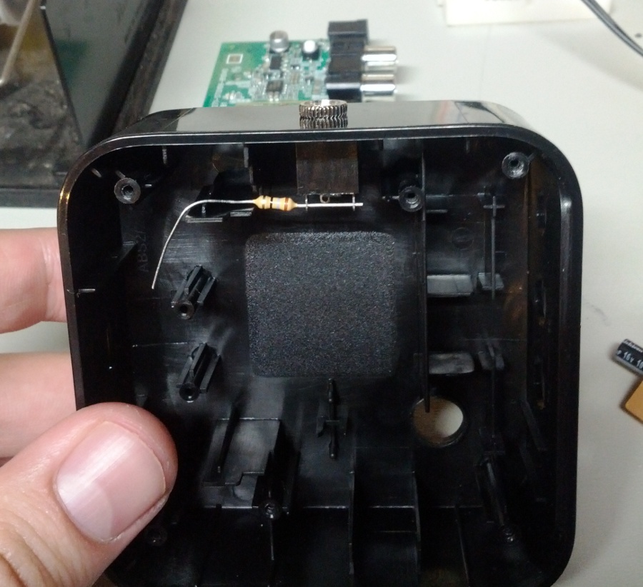
Only a little shrink-tube and some flying wires to the Logitech’s 3.3v power rails and TP14 was left to do.
Here’s the source code for the ATtiny25. It was originally developed on an Arduino and ported to the ATtiny25. It should be a quick port to any small 8-bit AVR. PB0 is for the Logitech’s LED input. PB1 should be attached to a N type transistor to drive your infrared LED. The AVR should be set to use its own 1Mhz internal RC clock.
Source: btirctl-v1.1.c
Binary: btirctl-v1.1.hex
Maximizes volume (0 dB) on connect and turns it down (-44 dB) on disconnect.
Much shorter delay between AUX command (power-on/switch input) and next action.
Source: btirctl-v1.c
Binary: btirctl-v1.hex